Schematic Module
This module is an interactive 3D of all the sites and how they connect with each other. It utilizes an intelligent content-sensitive display where it presents the necessary information you have to see based on the camera’s proximity to the site. Users can explore the interconnections between sites in a 3D environment, with the system intuitively displaying essential details as you zoom in or focus on specific areas.

- 1A. Jubilee Field and FPSO Kwame Nkrumah (KNK)
The Jubilee Field serves as the primary gas source for the Atuabo Gas Processing Plant.
- 1B. TEN Field and FPSO John Evans Atta Mills
The TEN Field functions as the secondary gas source for the Atuabo Gas Processing Plant.
Special Note: On specific occasions, gas from the Jubilee and TEN Fields is commingled. This occurs when the Gas Processing Plant’s (GPP)‘s heat medium system malfunctions, as the drier gas from the TEN Field can compensate for operational constraints.
- 2. Sankofa Field
The Sankofa Gas Project encompasses the development of the Sankofa and Gye Nyame gas fields located 60km offshore of Western Ghana in water depths ranging from 520m to 1,014m in the Tano Basin.
- 4. Main Gas Pipeline
The gas export manifold connects to the Atuabo Gas Processing Plant through the main gas pipeline, ensuring the steady transport of commingled or independent gas streams to the plant for processing.
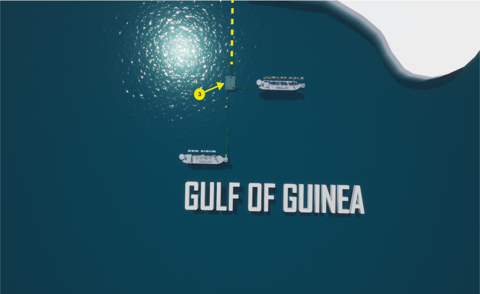
- 3. Gas Export Manifold
This is the commingling point where gas from the Jubilee and TEN Fields is blended. The manifold ensures seamless integration and efficient distribution of gas supplies to the processing plant.
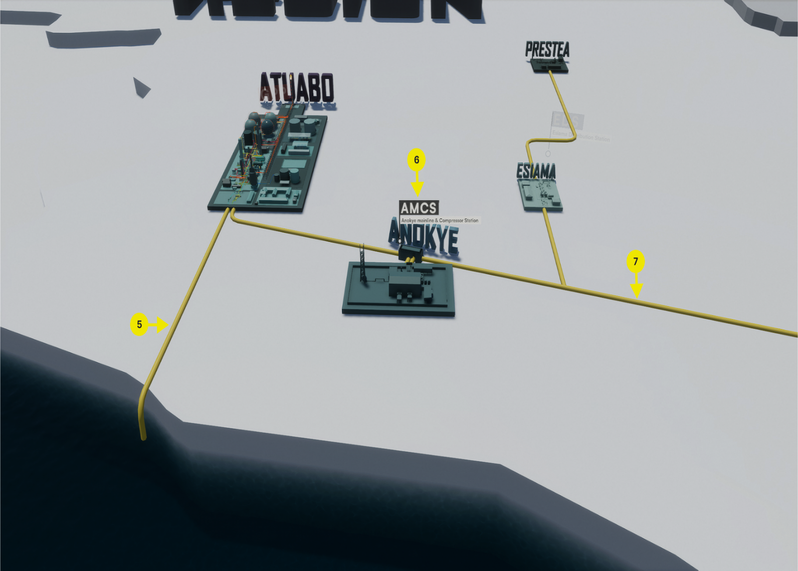
- 5. Main Gas Pipeline Continuation
This segment represents the continuation of the main gas pipeline linking the Gas Export Manifold to the Atuabo Gas Processing Plant.
- 6. Station Names Display
This feature shows the names of various stations. Users can select a station to access detailed and comprehensive information about its operations and functionality.
- 7. Main Pipeline for Sales Gas
This pipeline contains sales gas and serves as the primary connection between the various stations, facilitating efficient distribution across the network.
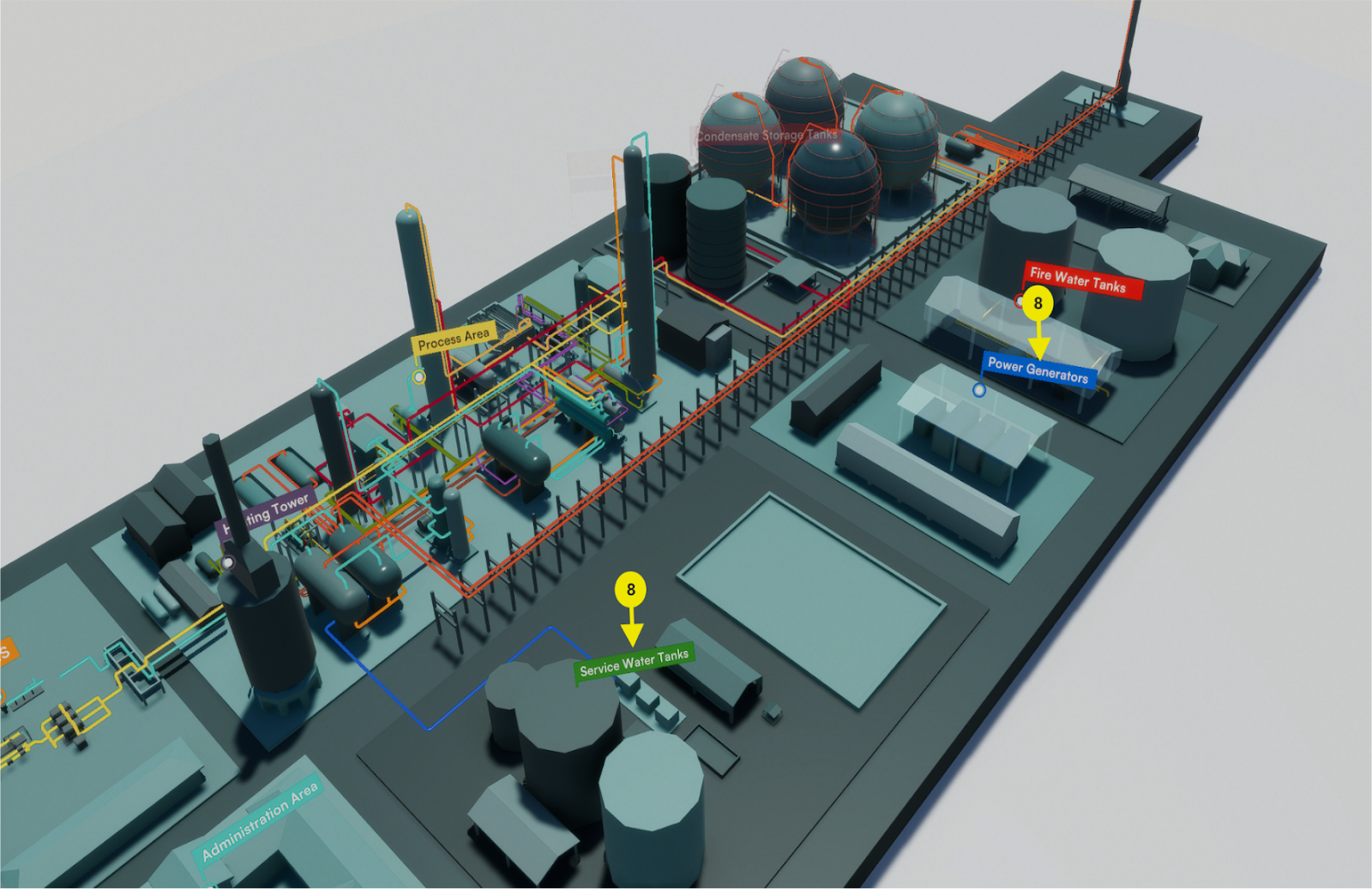
- 8. Site Zoom and Section Identification
When a user selects and zooms in on a site, the major sections of the site become visible. The arrow highlights these key sections and displays their respective names, providing a clear and detailed view of the site’s layout.
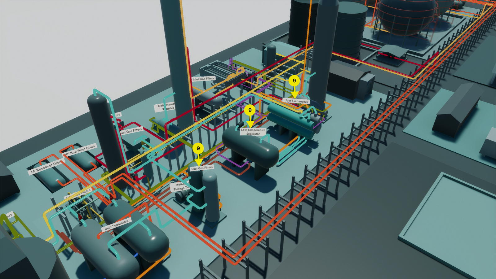
- 9. Major Equipment Display
The major equipment at the site becomes visible at this stage based on the camera’s proximity during zooming. The arrow highlights the major equipment and displays their respective names, providing a detailed account of the site’s operations.

- 10. Equipment Details Display
When a user selects and zooms in on a specific piece of equipment, the intricate details and components become visible. At this stage, the detailed process flow within the selected equipment and the site legend becomes displayed.
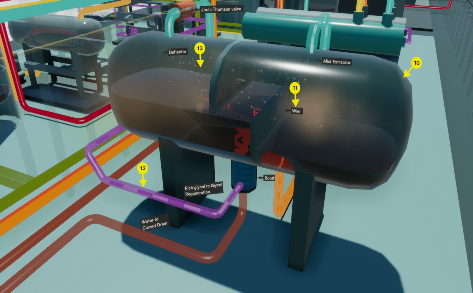
- 11. Component Identification
The arrow highlights the main components of the equipment, along with their respective names. This provides detailed insights into the operation and functionality of the equipment.
- 12. Animated Process Stream
Displays the animated, color-coded process stream of the site, offering a visual representation of the flow and behavior of materials through the system.
- 13. Particle Simulation
This feature provides an internal simulation of particles within the process feed, showcasing the dynamic behavior of materials as they move through the equipment.
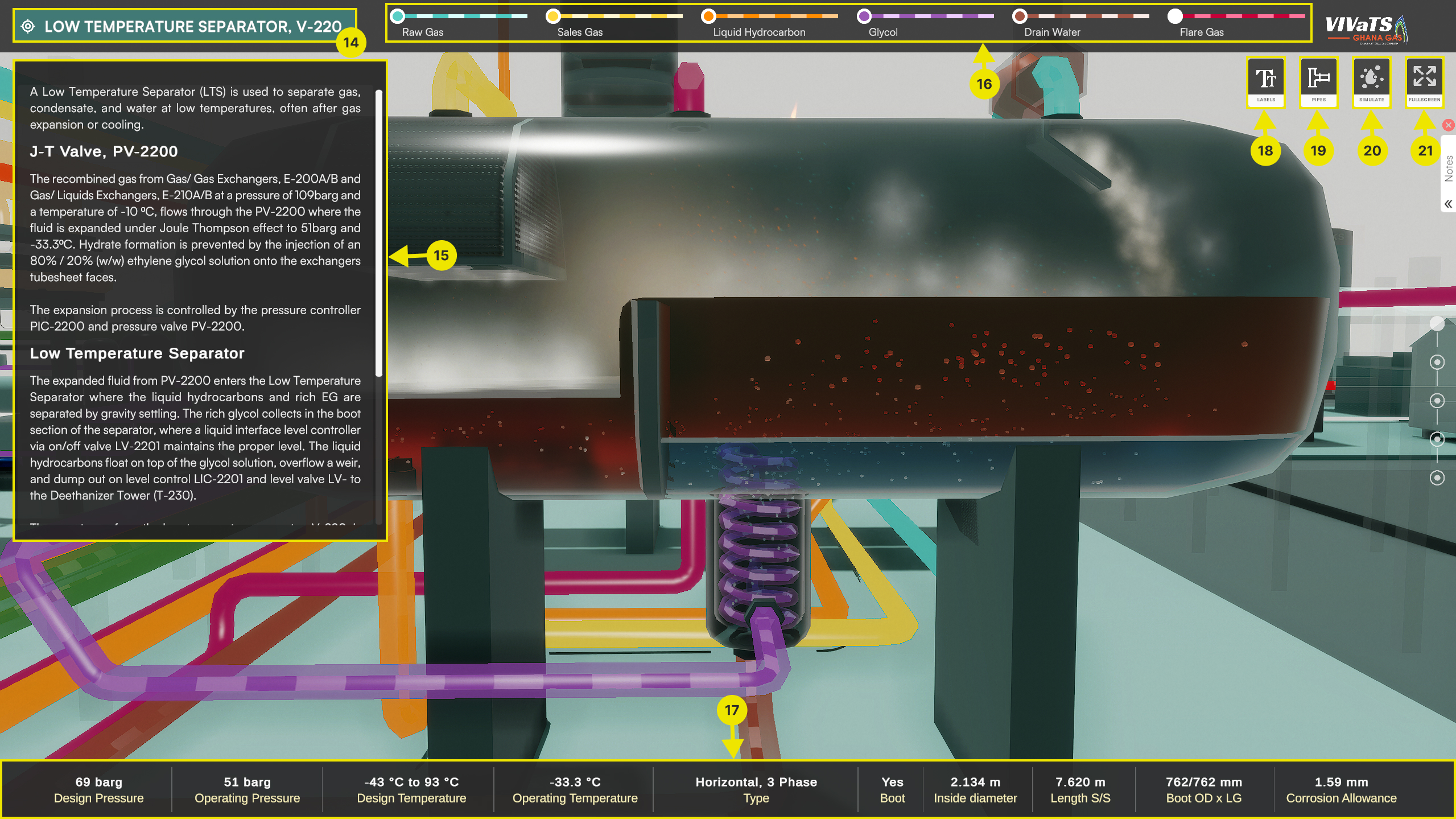
- 14. Equipment Name
It displays the name of the equipment currently in focus. It is part of the Smart Overlay Display, which activates when the view zooms in on a specific piece of equipment. It appears alongside components numbered 15 - 20.
- 15. Information Panel
Displays detailed information about the equipment currently in focus.
- 16. Process Stream legend/toggle
A quick-reference legend that highlights the process streams associated with the equipment currently in focus. It includes toggles to show or hide specific streams for emphasis.
- 17. Operating Conditions
Displays the operating conditions of the particular equipment in focus.
- 18. Text labels button
Used to hide or show the labelled parts of the current equipment in focus
- 19. Pipes button
Enables toggling the visibility of all pipes connecting equipment in the plant. This is especially useful for clearing pipes that may obstruct key views, given their abundance.
- 20. Animation/Simulation button
Used to pause or resume the flow all all process steams in the various process vessels and connecting pipes.
- 21. Fullscreen button
Used to toggle toggle the visibility of all UI elements for a more immersive view of the equipment.
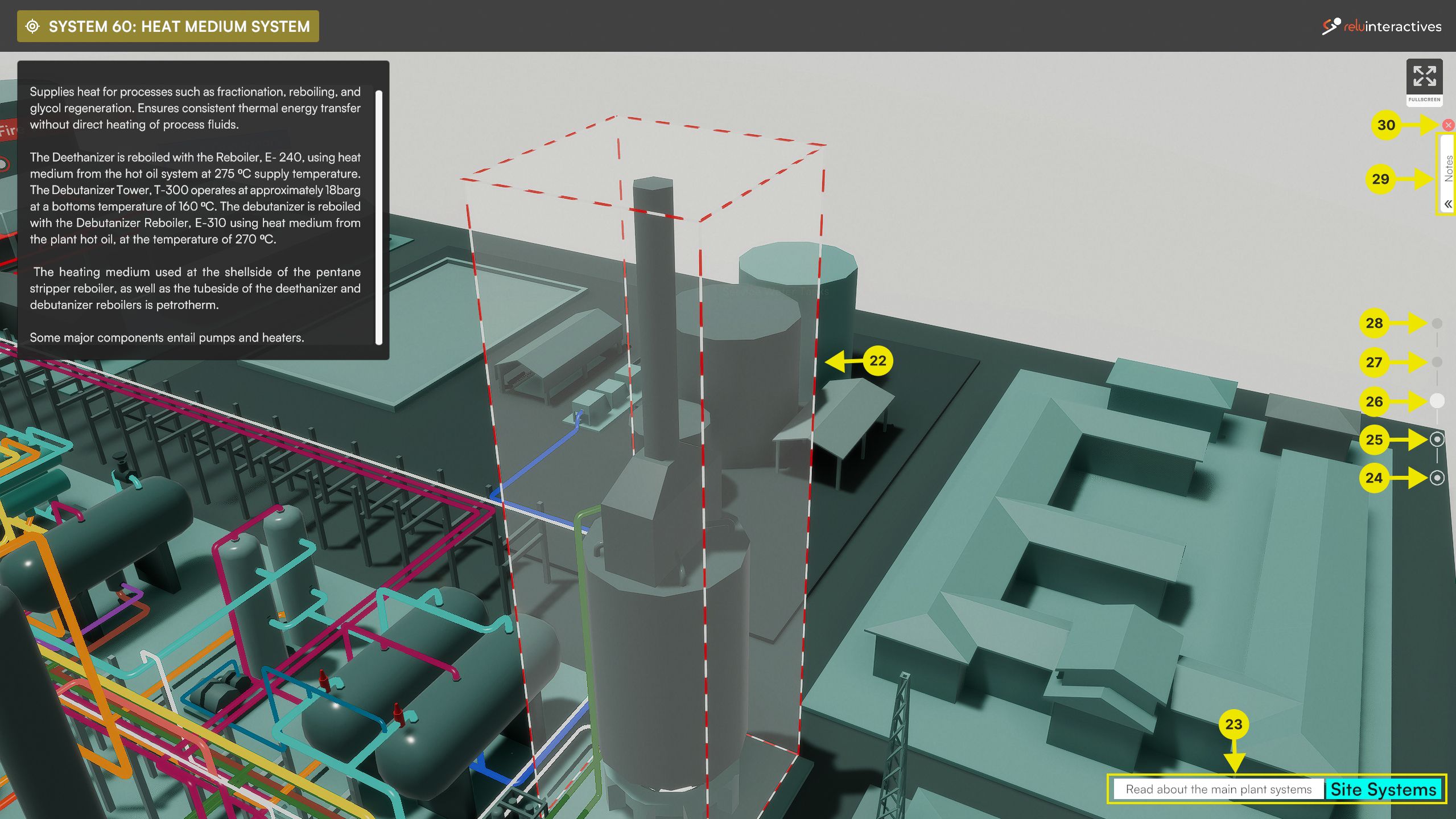
- 22. Site Systems highlight
Systems are groups of equipment that work together to perform a unified operation. The Site Systems highlight outlines these equipment groups and provides relevant information about their functionality.
- 23. Zoom Level Information
The software operates across multiple zoom levels and uses smart overlays to deliver relevant information at each level. The Zoom Level Information offers quick tips on what to do or expect at each zoom level. There are five discrete zoom levels: Sites, Site Sections, Site Systems, Equipment, and Equipment Parts. These levels are represented and controlled by five zoom icons, numbered 24–28 below. Each zoom icon serves as both an indicator and a control button.
- 24. “Sites” zoom display and Quick jump button
“Sites” is the first zoom level, and its icon is highlighted when the view is set to this level. When viewing at other zoom levels, clicking this icon will quickly zoom out to the Sites level.
- 25. “Site Sections” zoom display and Quick jump button
“Site Sections” is the second zoom level, and its icon is highlighted when the view is at this level. Clicking on this icon from other zoom levels will quickly zoom in to the Site Sections level.
- 26. “Site Systems” zoom display and Quick jump button
“Site Systems” is the third zoom level, and its icon is highlighted when the view is at this level. Clicking on this icon from other zoom levels will quickly zoom in to the Site Systems level.
- 27. “Equipment” zoom display and Quick jump button
“Equipment” is the fourth zoom level, and its icon is highlighted when the view is at this level. Clicking on this icon from other zoom levels will quickly zoom in to the Equipment level.
- 28. “Equipment Parts” zoom display and Quick jump button
“Equipment Parts” is the final zoom level, and its icon is highlighted when the view is set to this level. Clicking on this icon from other zoom levels will quickly zoom in to the Equipment Parts level.
- 29. Notes
This container holds personal notes for future reference while using the software. To add a note, simply right-click on any part of the equipment in the viewport.
- 30. Close Application button
This button opens a dialogue box to confirm closing the application. It functions the same as pressing the Escape key.
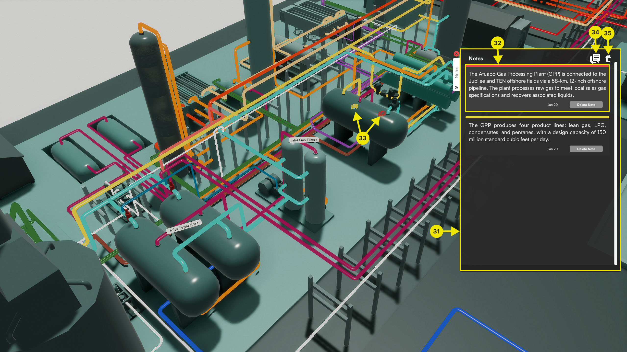
- 31. Notes Thread
This is where all the note slips are stored in a thread.
- 32. Note Strip
Each note is stored in a note strip, featuring a unique colour, the date it was added, a delete button to remove the note, and a note anchor (numbered 33 below) for reference.
- 33. Notes Anchor
This icon appears at the location where the note was added in the software viewport, linking the note to the specific area that inspired it.
- 34. Note Anchors visibility toggle
This toggle controls the visibility of Note Anchors in the viewport. It is particularly useful when too many notes are added, preventing them from obstructing areas of interest on the screen.
- 35. Delete all Notes button
Used to clear the Notes thread of all Notes strips.